A TCXO is a temperature-compensated crystal oscillator that is used whenever particularly high stability within a variant temperature environment is required, i.e. when the frequency deviation of the oscillator must be minimal over its entire operating temperature range.
Oscillators using AT quartz crystal plates, so called “blanks”, are the most economical solution to create a stable and precise reference frequency. However, their frequency accuracy varies depending on the ambient temperature. At a temperature of 25°C, accuracy is at its highest. The further away the ambient temperature is excursive from 25°C, the frequency deviation will be changed according to a specific characteristic.
The relationship between temperature and frequency deviation can be approximated using a 3rd degree polynomial function. A 5th degree function can also be used for a more accurate curve fit.
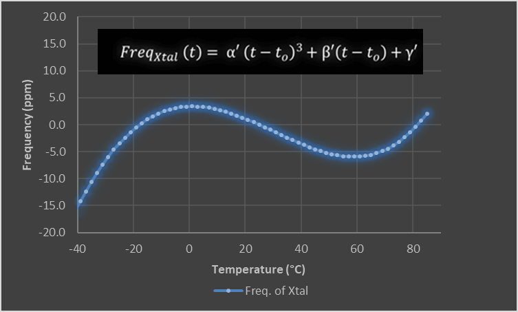
Under extreme temperature conditions, frequency deviations of up to +/- 100 ppm maximum occur with a normal quartz oscillator (XO) given that higher degree polynomial coefficients are more apparent in the extreme temperature ranges. The frequency stability of normal XOs, as it is illustrated in Figure 1 above, is completely sufficient for numerous applications. However, there are many others as for example wireless- or GPS-applications that make significantly higher demands, that can merely be met by TCXOs.
Design and Functionality of a TCXO
TCXOs constrain frequency deviations over the entire operating temperature range between -40°C to 85°C, thus achieving a frequency stability of up to ± 0.5ppm.
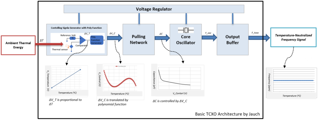
In the following, the functionality of a TCXO will be explained in detail by taking a closer look at its basic architecture. Usually, a TCXO consists of five functional blocks (Fig. 2), that will each be described in more detail below.
1) Controlling Signal Generator with Polynomial Function
The controlling signal generator is the heart of a TCXO. In a first step, it observes the changes of ambient temperature (ΔT) with the help of a built-in temperature sensor. Using a comparator with predefined reference voltage, the sensed temperature (ΔT) will be translated into a proportional temperature voltage (V_T). In a next step, the temperature voltage (V_T) is translated into a specific controlling voltage (V_C), using a polynomial function generator.
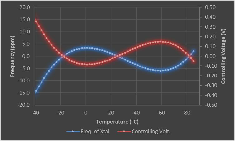
Summing up, you can say that the controlling voltage V_C (red curve) follows a predefined processing, reflecting the temperature perception of the oscillator (blue curve). However, as all crystal blanks have individual temperature characteristics, a piece-by-piece compensation process is necessary to determine the coefficients of the polynomial function for every individual blank. As a consequence, TCXOs are particularly precise but also more expensive than other types of oscillators.
2) Pulling Network
This circuit uses the controlling voltage (ΔV_C) to correct the frequency deviation of the oscillator caused by temperature changes.
To understand how the controlling voltage can calibrate the frequency, it is helpful to take a look at the following equation:
\[ fosc=1/(2*pi*\sqrt(L*C)) \]Accordingly, the oscillator’s resonant frequency (fosc) is determined by two equivalent variables: the equivalent inductance (L) of the quartz and the equivalent capacitance (C). As a natural property of any quartz blank, inductance (L) varies as temperature changes. Compensating these changes is thus only possible by adjusting the capacitance (C), that is controlled by the ASIC.
An array of varactors is used to neutralize the temperature effect of the crystal blank by complementarily altering the capacitance (Δ_C). As temperature rise causes a rise in equivalent inductance (L) of the crystal blank, the equivalent capacitance (C) will complementary be pulled down by the array of varactors.
Varactors change their capacitance according to voltage, so at this point the abovementioned controlling voltage (V_C) comes into play. Put simply, the array of varactors uses the controlling voltage (V_C) to adjust the equivalent capacitance (C) in a way to counteract the variation of the resonant frequency of the individual crystal blank at variable temperatures.
3) Core Oscillator
In addition to these temperature compensation circuits, a TCXO naturally also has an ordinary oscillator circuit that is optimized to generate the desired frequency.
4) Voltage Regulator
This component is a kind of “protection mechanism”. The aim is to regulate the voltage applied to the TCXO from outside in order to prevent any voltage fluctuations within the TCXO, caused for example by the noise of the power supply.
5) Output Buffer
Another kind of protective mechanism. It isolates the crystal oscillator from any external load changes. Therefore, the variation of output-load capacitance would not impact the accuracy of resonant frequency.
TCXO: Typical Fields of Application
Thanks to their enormous frequency stability, TCXOs are particularly suitable for wireless applications in telecommunications. The components are also in great demand in the IoT sector, GPS-applications and numerous consumer products.
Since every application has its own specific requirements, Jauch Quartz offers a wide range of TCXOs in different sizes with its JT-series. This portfolio has lately been complemented by the introduction of the new JT21G, that has been specially designed for the use in navigation systems (GPS, GNSS etc.).
All components of the JT-series are equipped with either an HCMOS or a Clipped Sine output. In addition, all components of JT-series are characterized by two important core features.
Jauch-TCXO use Disciplined Quartz Blanks only
Ordinary quartz blanks may have minor defects or impurities, such as an insufficiently polished area on the quartz surface or disordered lattices in the crystal blank. These minor irregularities can potentially cause a prompt frequency jumping at a particular temperature range, that cannot be described by a finite-degree polynomial equation. As a consequence, the compensation-mechanism of the TCXO will be inaccurate at this particular temperature range. This phenomenon is called “frequency perturbation” and is visualized in figure 4 below.

Figure 4 shows the temperature characteristics of a TCXO using an ordinary quartz blank with an unexpected frequency perturbation at 63°C. So, if the operational temperature comes close to this critical temperature point, a sudden jump of the output frequency will occur. A system driven by this inaccurate frequency will show a deterioration or even malfunction at least temporarily. As a consequence, Jauch only uses high-quality quartz blanks and sophisticated crystal design to avoid any kind of frequency perturbation of our TCXOs.

Real-Time Reaction Thanks to Mixed Signal ASIC
Jauch-TCXOs are controlled by a mixed-signal ASIC. The parameters in the five functional blocks are therefore settled digitally. In contrast, the compensation mechanism, i.e. the translation of the perceived temperature into a correction voltage, is purely real-time analog method and thus – in contrast to the digital alternative – without delay or limited resolution.
A sophisticated temperature compensation mechanism and the usage of high-quality quartz blanks ensure enormous frequency stability, thus making Jauch-TCXOs the ideal solution for a wide range of applications in the wireless and telecommunications sector as well as demanding navigation systems.
Are you looking for the right TCXO for your application or do you need design-in support? Don`t hesitate to contact us! We will be happy to help you finding the optimal solution!


 Deutsch


